+604 332 2335
sales@professional-tools.com
+604 332 2335
sales@professional-tools.com


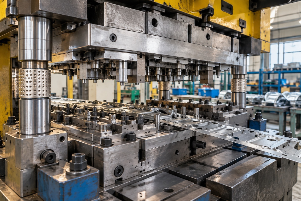
For an automotive stamping programme, a die that produces an acceptable first-off part is only the starting point. The harder question is whether the tooling can hold the specified dimensions, surface condition and process stability through the intended production run. That depends on the component design, sheet material, press conditions, die construction, inspection plan and maintenance strategy.
This guide explains how automotive manufacturers and purchasing teams can evaluate high-precision sheet metal stamping dies, from early design-for-manufacture reviews to die tryout and production approval. It is an engineering and procurement guide, not a claim about an undisclosed customer project or a guaranteed tolerance.
A stamping die is tooling fitted to a press to cut, bend, form or otherwise shape sheet metal. Precision is not defined by a single advertised tolerance. It means the tooling and process can repeatedly produce the specific part characteristics required by the drawing, within an agreed measurement and production framework.
Automotive components may include brackets, reinforcement parts, covers, clips and other formed or blanked components. Different features carry different risks: a mounting hole may require positional control, a flange may require angular control, and a mating surface may require flatness or profile control. The critical characteristics should be identified before the die concept is finalised.
Die accuracy and finished-part accuracy are related but not identical. Sheet material properties, elastic recovery (springback), press alignment, lubrication, tool wear and measurement methods can all affect the produced part.
Before requesting a tooling quotation, the buyer and die maker should align on the information that determines feasibility, cost and risk.
| Input | Why it matters | What to confirm |
|---|---|---|
| Released part drawing and CAD | Defines geometry, datum scheme and controlled features | Drawing revision, GD&T, critical-to-quality features and inspection datums |
| Sheet material specification | Influences formability, springback, cutting load and tool wear | Grade, thickness range, coating, mechanical-property range and supply condition |
| Annual and peak demand | Influences die architecture, automation and maintenance planning | Expected volume, batch sizes, ramp-up and programme life |
| Press and handling constraints | Determines fit and process integration | Press capacity, bed dimensions, stroke, shut height, feed and part transfer method |
| Acceptance and quality plan | Prevents disagreement over whether tooling is production-ready | Tryout criteria, sample quantity, measurement method, capability evidence and approval responsibility |
For safety-related or tightly controlled parts, the customer should also communicate any applicable automotive customer-specific requirements, traceability expectations and formal production-part approval process. A supplier’s ability to meet these requirements must be verified for the particular programme.
There is no universally best die design. The correct choice depends on geometry, material behaviour, production rate, press capability, handling and lifecycle cost.
| Die approach | Typical use | Main trade-off |
|---|---|---|
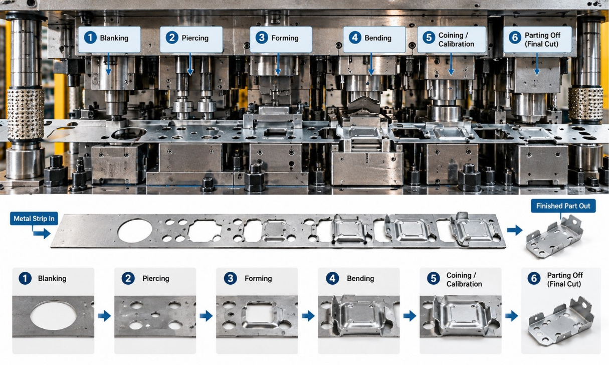
| Progressive die | Several operations performed sequentially on a continuous strip | Efficient repeat production, but strip layout, feed accuracy and scrap must be managed |
| Transfer die | Parts moved between stations for successive operations | Can suit more complex formed parts, but handling and press integration add complexity |
| Single-station or compound die | Defined operations in one station or press stroke | May simplify tooling for selected parts, but additional handling or operations may be needed |
For example, a relatively small bracket with several pierced and formed features may be a candidate for progressive tooling. A large, deeply formed component may require a different forming and transfer strategy. These are screening examples, not substitutes for a feasibility review.
Automotive sheet metals can behave differently even at the same nominal thickness. Yield strength, tensile strength, work hardening, anisotropy and coating condition can influence forming loads, thinning, wrinkling, cracking and elastic recovery.
Springback occurs when a formed part elastically recovers after the tooling load is removed. It may change flange angles, profiles and assembly fit. Engineers can address it through suitable die geometry, forming sequence, restraint and process development, but the effectiveness must be confirmed in physical trials using representative production material.
Forming simulation can help identify likely strain concentrations and springback risks before steel is cut. It does not remove the need for die tryout, material verification and measured part approval. A quotation should distinguish between simulation offered, simulation completed and simulation validated against trials.
Where the automotive customer requires a formal Production Part Approval Process (PPAP), the submission level, evidence and acceptance criteria should be agreed with that customer. A successful die trial alone is not equivalent to PPAP approval.
A claim such as “precision to ±0.05 mm” is not meaningful without identifying the feature, material, process conditions, measurement method and statistical basis. A die may hold a tight tolerance on one punched feature while another formed feature has a different requirement.
Buyers should ask for a feature-based inspection plan. Depending on the part, inspection may involve calibrated gauges, CMM measurement, optical methods, profile checks or functional assembly checks. For repeat production, process capability should be assessed using the agreed sampling method and stable operating conditions, rather than inferred from a handful of first-off samples.
Also distinguish tool inspection from stamped-part inspection. A die component measuring correctly does not by itself prove that every finished part characteristic is in tolerance.
| Observed issue | Possible contributors | Practical next check |
|---|---|---|
| Flange angle or profile out of tolerance | Springback, material variation or forming sequence | Compare measured parts with drawing datums and representative material properties |
| Burrs at pierced or blanked edges | Cutting clearance, edge wear or alignment | Inspect cutting edges, clearance and burr acceptance criteria |
| Wrinkling or splitting | Material flow, restraint, radii or lubrication | Review strain/forming conditions and actual material batch |
| Dimensional drift during a run | Tool wear, feed variation, press condition or temperature | Trend measurements against cycle count and inspect the press-tool interface |
| Surface marks or coating damage | Contact pressure, debris, tool finish or handling | Inspect contact areas and agreed cosmetic or coating requirements |
These are diagnostic starting points. The actual root cause should be established through controlled inspection and trials rather than assumed from appearance alone.
Maintenance is part of production capability, not an afterthought. The plan should identify inspection points, lubrication needs, wear components, cleaning requirements, safe handling and criteria for tool repair. The appropriate interval depends on the tool, material, production volume and observed wear; no single cycle-count rule applies to every die.
Record interventions alongside part-quality trends. If burr height, dimensions or press behaviour begin to change, maintenance teams can use that evidence to determine whether cutting edges, guides, locating components or other parts need attention. Any repair that changes functional tooling geometry may require renewed part validation.
These questions are particularly useful when comparing quotations that appear similar on price but differ in engineering scope, tryout responsibility or production support.
Professional Tools & Dies Sdn. Bhd. presents mould and die fabrication, sheet metal stamping, CNC machining and turning, and sheet metal fabrication among its manufacturing services. For buyers coordinating tooling and subsequent component manufacture, discussing these processes together may help identify interfaces and responsibilities early in the project.
However, the suitability of any supplier for a specific automotive programme must be established from the actual drawing, material, volume, equipment requirements, inspection capability and customer approvals. This article does not imply that a particular automotive OEM project, tolerance result or certification has been independently verified.
If your requirement involves production fixtures or part location during manufacturing rather than the stamping die itself, discuss jigs and fixtures as a separate tooling scope. They support repeatable positioning and inspection but are not interchangeable with stamping dies.
For related background, read the company’s comparison of sheet metal stamping and other fabrication methods or its beginner’s guide to sheet metal fabrication in Malaysia.
For project-specific requirements, the customer’s controlled drawings and applicable standards take precedence. The following organisations publish useful background on forming, materials and automotive production approval:
It is tooling used in a press to cut or form sheet metal into automotive components. Its design must suit the part geometry, material, press and required production volume.
No. Progressive dies can be effective for suitable strip-fed components, but transfer or other die arrangements may be preferable for certain geometries and forming sequences. The choice requires a feasibility and lifecycle-cost review.
Finished-part dimensions also depend on material variation, springback, press conditions, tool setup, wear and measurement methods. Tool accuracy alone does not guarantee part conformity.
Not necessarily. The customer may require additional dimensional results, process studies, documentation and formal approval, such as a specified PPAP submission.
Provide the current drawing and CAD revision, material grade and thickness, forecast volumes, press constraints, critical characteristics, target timing and required quality or approval documents. Clarify confidentiality and data-sharing arrangements before sending controlled designs.
When evaluating a die-making partner, begin with the part requirements and acceptance criteria—not an unqualified precision claim. Review Professional Tools & Dies’ sheet metal stamping services and company website to discuss the scope of your tooling and manufacturing enquiry.